CPU-Z is a very popular system profiling tool for windows that provides details about various hardware components including cpu, ram, motherboard and graphics card. If you want to quickly check the make, model, brand or specifications of the hardware components on your machine, then cpu-z will show those details right away.
It is not as powerful as HwInfo which can report a huge lot of details. But for basic checkup it is an excellent tool.
In this quick tutorial we shall take a look at various hardware specifications reports by cpu-z in the memory section and see what each of the parameters mean. Most newbies have no knowledge of what these hardware metrics mean or indicate, and that is why we are elaborating things here.
You can download cpu-z for free and launch it. Switch to the "Memory" tab and you shall see a lot of details. Below you can read a detailed guide on what each of the details mean.
1. Channel # - Number of Memory Channels
This shows the number of channels where memory has been installed along with the width of the address bus. For example:
For instance my Asus TUF A17 gaming laptop shows:
2 x 64-bit
It implies thats the memory is installed in 2 channels of address width 64bit each. Each channel might comprise of one or more DIMM slots. On laptops typically there are only 2 SODIMM each assigned to a separate channel. On desktops motherboards there can be 4 DIMM slots, divided into 2 channels with 2 DIMM slots each.
If you have 4 sticks of ram installed in 4 dimm slots on your motherboard it would still show something like 2x64-bit.
The number of channels is usually determined by the cpu right away. Most consumer cpus support only 2 channels, whereas high end workstation cpus like threadripper support 4 or more.
Incorrect information: However the information might not be correct everytime. My Acer Swift 3 laptop shows the following.
4 x 64-bit
The above makes it look like the ram is spread across 4 channels, whereas actually its only in 2 channels. This sort of inaccurate information shows up on laptops with onboard soldered memory.
2. Uncore Frequency
"Uncore" refers to the non-cpu-core parts present in the cpu, like the memory controller/cache/CPU NB/SOC that run at their own independant clock frequencies other than the cpu core frequency.
The uncore frequency is in no way related to the ram frequency. It can be any value that is very different from the "DRAM Frequency" as reported by cpu-z.
On intel cpus it controls the frequency of the RING/Last Level Cache. On Ryzen cpu systems, the uncore frequency will often be exactly equal to the dram frequency. When overclocking the dram frequency to higher values, the uncore frequency also increases.
In the following screeshot note that Uncore Frequency = DRAM Frequency. This machine has 5800h ryzen cpu with 16gb dual channel ram.
The uncore frequency can also throttle depending on the cpu load. When the cpu load is very low/minimal, the uncore frequency will drop to half of its regular value.
On my Acer Aspire 5 (5500U) the uncore frequency is at ~800 Mhz when cpu is nearly idle, and increases to ~1600 Mhz when cpu is under load.
Also the value of uncore frequency were not the same as FCLK (Infinity Fabric Clock) and UCLK (UMC CLK - Unified Memory Controller clock) as checked with hwinfo64. This implies that ucore is not the same as UCLK
On some systems the motherboard will put the uncore in a kind of overclock mode which locks and prevents its frequency from coming down and increases performance though consumes a little more power.
More information can be found at this wikipedia article: https://en.wikipedia.org/wiki/Uncore
Intel CPUs:
On intel cpu system the uncore frequency refers to the frequency of the cache which often operates at frequencies close to that of the cpu. Hence the value will often very high and close to the cpu frequency.
As per hwinfo64 on Intel i5-1135G7 laptop:
Bus Clock x Uncore Ratio = Ring/LLC Clock
And the Ring clock goes as high as the cpu max clock, depending on the cpu load.
This implies that the Uncore frequency affects the Ring/Last Level Cache clocks on Intel cpus. On Intel cpus the Last Level Cache may be considered L3 cache.
AMD cpus
On the amd cpus the uncore clock works in a very different way. The uncore freq. on amd cpus is usually equal or half of the dram frequency.
It will also be related to / affect (though not exact) to the values of MCLK/FCLK/UCLK.
On my Acer Aspire 5 laptop (5500U) laptop the uncore freq is a fractional multiple of MCLK/FCLK/UCLK
| CPU State | MCLK (Mhz) | FCLK (Mhz) | UCLK (Mhz) | Uncore Freq. (Mhz) |
| CPU Idle | 800 | 400 | 400 | 800 |
| CPU Load | 1200 | 1200 | 1200 | 1600 |
| CPU State | MCLK (Mhz) | FCLK (Mhz) | UCLK (Mhz) | Uncore Freq. (Mhz) |
| CPU Idle | 800 | 400 | 400 | 800 |
| CPU Load | 1600 | 1600 | 1600 | 1600 |
It seems that the cpu-z uncore freq. is an irrelevant metric for amd cpus and only the FCLK/UCLK/MCLK matter. The values of FCLK/UCLK/MCLK can be checked using ZenTimings on ryzen systems.
With MCLK (Memory Clock) and FCLK (Infinity Fabric Clock) are in a 1:1 ratio, the ram runs with the lowest latency. UCLK is (UMC Clock) is often synced with FCLK, so is the same value as FCLK.
The uncore frequency is also affected by the power profile and hardware setup of the system. For instance when my Asus TUF A17 is on battery mode, the uncore freq. drops to 800 Mhz unless cpu load is high. However when on ac power supply the frequency stays at 1600 Mhz even when the cpu is idle.
On my Asus TUF A17 when I connect external monitor via the dGPU port, the MCLK/UCLK/FCLK/Uncore all stay high, even when cpu is relatively idle.
On desktop systems the values of MCLK, FCLK, UCLK can be modified for overclocking the system with motherboards that support it.
Mem Controller Freq.
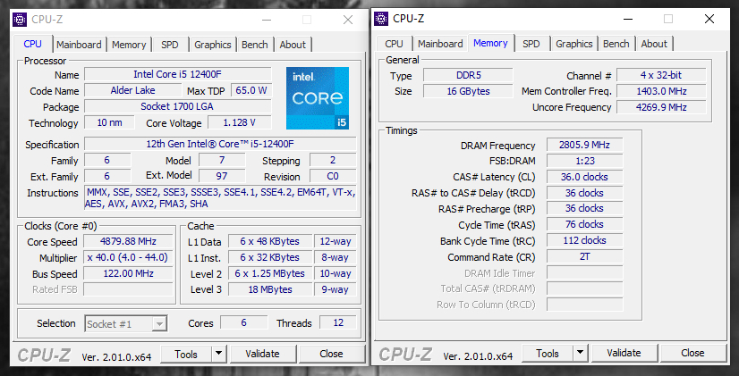
This is seen on intel cpu computers. It is the clock frequency of the memory controller inside the cpu. It can be some lower multiple of the DRAM frequency like 0.5 (half). The memory controller frequency is multiplied by a certain "FACTOR" which determines the actual frequency the DRAM will run at. By adjusting the multiplier, the system can throttle the speed of the ram depending on performance needs and power saving requirements.
Usually when a system is idle, various clocks on a system slow down in order to save power and produce less heat. When under load the system will boost all clocks and multipliers to higher values.
The ratio of the dram freq. to the memory controller frequency is called IMC Gear Mode, which is specific to intel cpus.
NB Frequency (North Bridge)
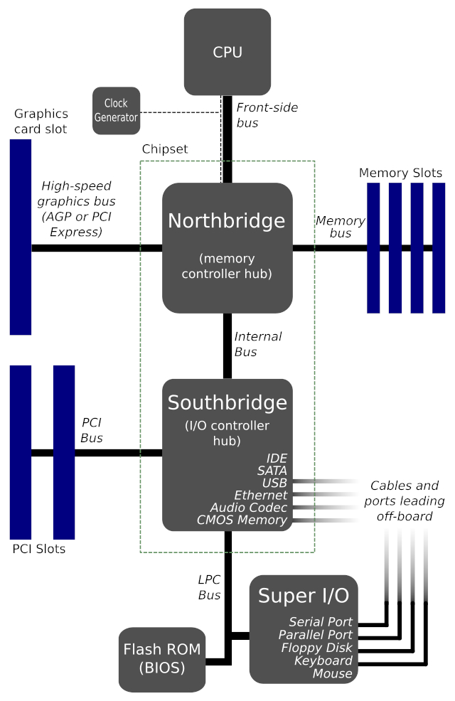
Some systems will show a field termed NB Frequency. NB stands for North Bridge, which is nothing but the memory controller present inside the cpu now a days. So NB Frequency is just the memory controller frequency.
In older systems (made before 2008 or so) the North Bridge (memory controller) was part of the chipset. But in modern systems the memory controller is now integrated inside the cpu itself. So in a way the cpu is directly connected to the ram.
Source: Wikipedia
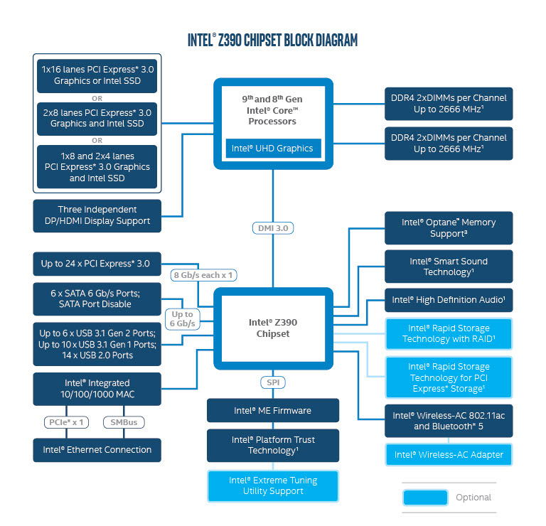
Modern intel systems have a different layout. Here is an example
Source: Intel
3. DRAM Frequency
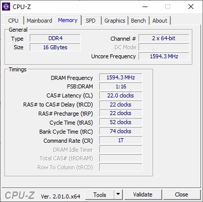
This the hardware clock frequency of the ram modules. Values like 1200 Mhz / 1600 Mhz / 2133 Mhz / 3200 Mhz are seen commonly.
The dram frequency when multiplied by 2 gives you the DDR transfer rates. For example:
1200 Mhz - 2400 MT/s
1600 Mhz - 3200 MT/s
The transfer rate is what you see in the Windows Task Manger as the speed. Windows incorrectly specifies it in Mhz, whereas its actually MT/s.
FSB:DRAM
This tells the ratio between memory reference clock and the actual frequency. It is the memory multiplier ratio.
For example:
DRAM Frequency = 2133 Mhz
FSB:DRAM = 3:64 = 1:21.33
Therefore reference clock is 2133 Mhz / 21.33 = 100 Mhz.
Or 100 Mhz x 21.33 = 2133 Mhz.
In other words, DRAM Frequency x FSB:DRAM = Reference clock.
Take another example
DRAM Frequency = 1600Mhz
FSB:DRAM = 1:16
Reference clock = 1600 Mhz x 1/16 = 100 Mhz.
In general this metric has no bearing to the performance of ram on the particular system and is included for historic reasons only. In early days, there used to be "Front-serial bus" in cpus which had the acronym FSB.
4. Timings
The timings are the most important
In general higher clock speeds need higher timings as well to maintain stability of the data residing in ram. This does not mean that the gains of higher clock speed is completely lost.
Timings are often discussed when overclocking ram, where users would increase system performance by lowering timings. However different systems respond differently to timing changes and lowering them too much can cause system instability and data corruption in memory.
Memory Read Sequence:
Activate Row -> Activate Column -> Read Data -> Refresh Row
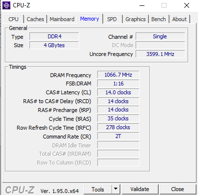
CAS Latency (CL)
"Column Access Strobe" Latency or CL for short, is the delay between when the memory controller requests a readback from the memory, and when the data in memory is actually available to the controller.
RAS to CAS Delay (tRCD)
It is the time required to open/activate the correct row (ROW-ACCESS-STROBE) which is not already open. If the row is already open from a previous request, tRCD will be minimal.
If data is requested from a row that is not already open, it will take atleast tRCD + tCL amount of time to fetch the first byte of data from that row. Subsequent reads from that row will be faster though with minimal impact of tRCD.
tRFC - Row Refresh Cycle Time
Time needed to refresh a row in a memory bank. Higher values provided stability and lower values increase performance. Users often report seeing better Low 1% FPS when tRFC is lower in value.
However lowering it too much will cause data corruption and might actually corrupt the underlying programs and files which are part of the operating system.
The value of tRFC can be checked with another tool called hwinfo64.
Command Rate
The value of CR shows in T (Ticks) like 1T or 2T. Obviously lower is better but it may not be supported on the system based on the ram and bios. A tick is basically 1 clock cycle and 1T takes one clocks cycle and 2T takes twice.
So a lower command rate increases system performance and this parameter can be tweaked in the bios for overclocking.
The 1t/2t is how many clocks the memory controller spends sending a given command to the ram. 1T means that the controller sends the command on one clock cycle, 2T means it sends it in 2 clock cycles.
Running 2T instead of 1T is like adding 1 to nearly every ram timing, though this is just an approximation.
For instance, running 1600-8-8-8-1T and running 1600-7-7-7-2T are very nearly identical, while 1600-7-7-7-1T is significantly (in benchmarks, at least) faster than either one.
On modern systems lowering the value from 2T to 1T might not bring any significant or noticeable boost in performance for regular applications and tasks. Intensive apps like games might notice some difference though.
SPD Data
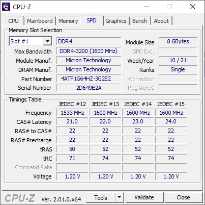
The next tab after Memory is the SPD tab, which is also related to ram. It shows ram bandwidth, manufacturer, model, module size, timings etc. Here is how the SPD tab looks on my Asus TUF A17 laptop.
There is a drop-down on top left that allows you to select the ram module in different slots, and view the details of that particular module.
Note: The SPD data is not available on laptops with onboard soldered ram, like the Acer Swift 3 laptop. SPD data requires the the spd chip which is installed on the ram modules.
In the above screenshot we can see that there are multiple JEDEC profiles, like JEDEC #12, #13, #14 and #15. Each of the profile has a different set of values for the operating parameters like the clock frequency, cas latency and other timing numbers.
Links and Resources
Ram Frequency and Timing Relation
https://www.overclock.net/threads/ram-timings-explained.381699/
https://www.overclock.net/threads/memory-timings-fully-explained.410205/
